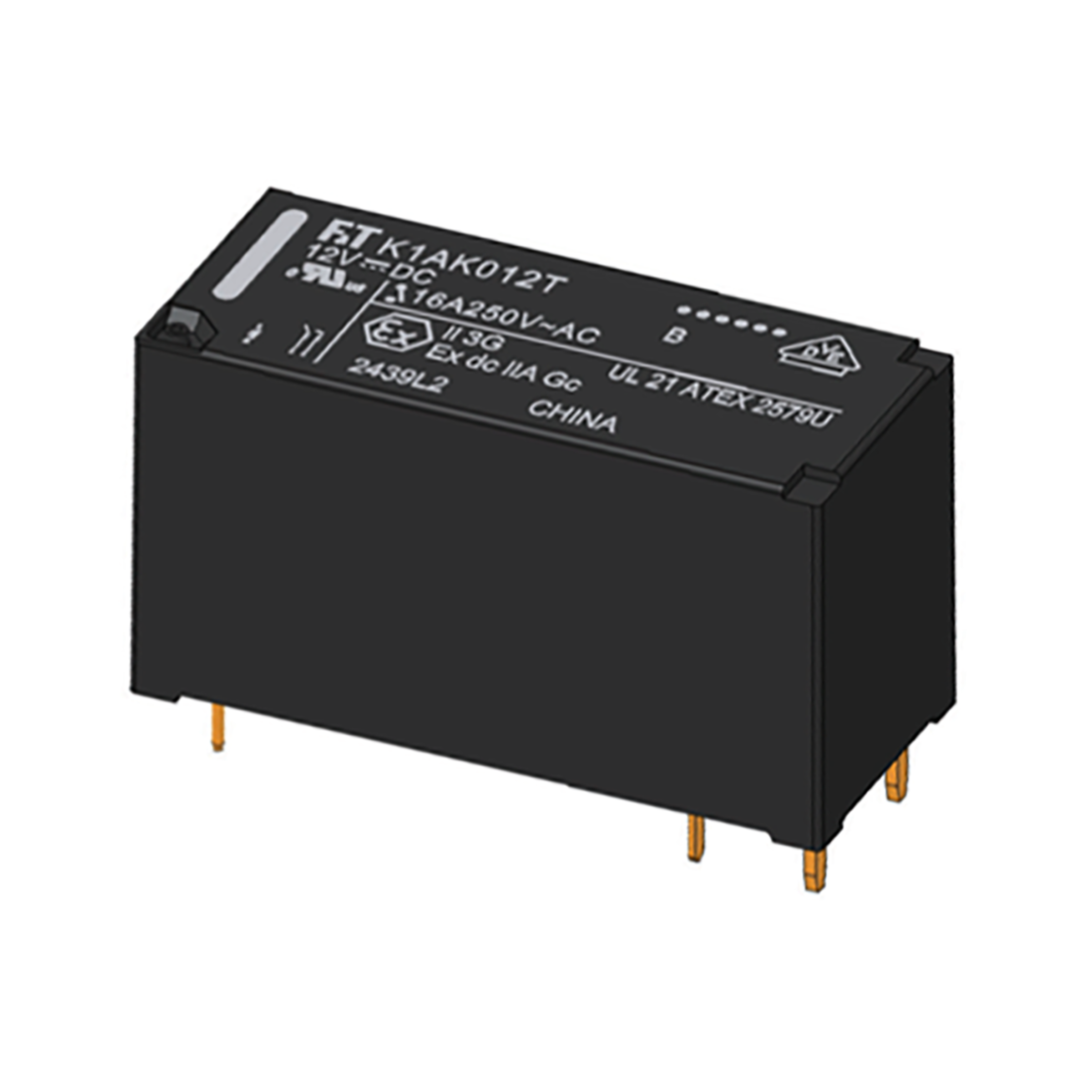
FTR-K1CK024W-EB
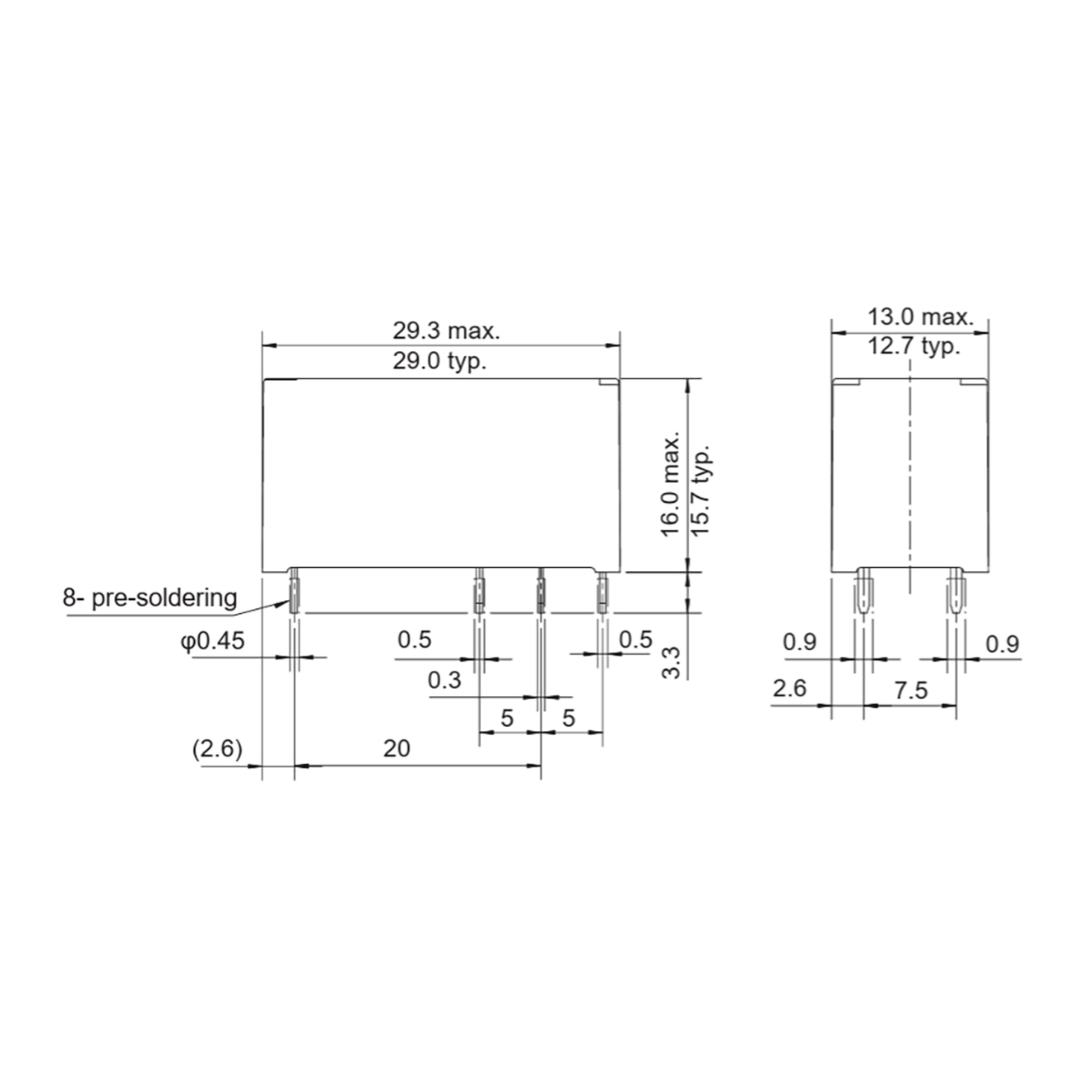
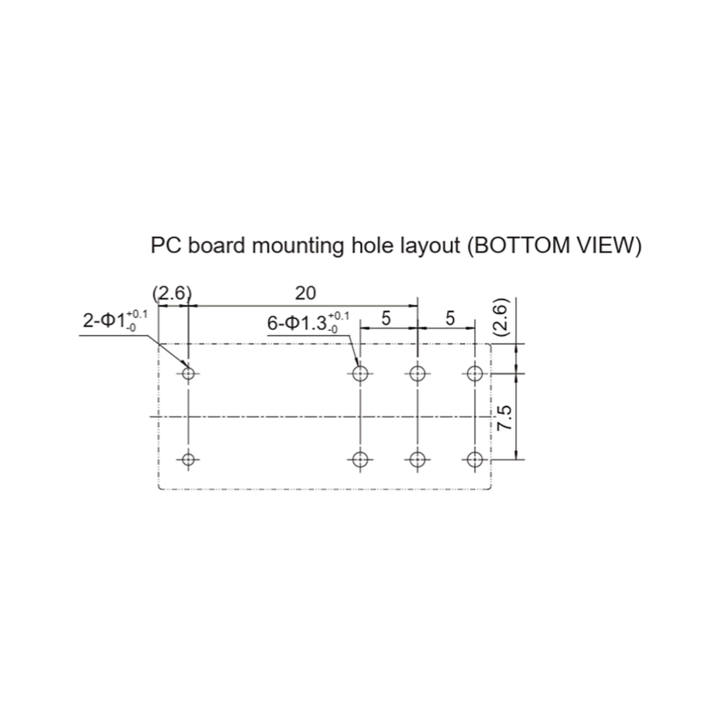
FCL Components PC relay FTR-K1 (ATEX) THT SPDT 16A 24VDC 1.440Ohm 29mmx12,7mmx15,7mm RTII
Enter your company's part number here. Your part number will be referenced on your receipts, such as the order confirmation, invoice or delivery note.
Enter your personal project number here to assign the item to a project. Your part project number will be referenced on your receipts, such as the order confirmation, invoice or delivery note.
250 Pcs. in stock
Planned delivery time
Ø 24 Weeks
Life Cycle Status
The life cycle indicates which market phase the item is in. We distinguish between:
• Active (green)
• NRND = Not Recommended for New Designs (yellow)
• LTB = Last Time Buy (yellow)
• EOL = End of Life (red)
Active
Available (from stock)
Data Sheet
ECAD Model
Prices
Manufacturer bundle 250 Pcs.
Manufacturer's packaging unit (Mfr. PU) means the smallest original packaging unit of the manufacturer.
Price per 1 Pcs.
Quantity and Options
(at least 10 or multiple of 10)
All prices net plus VAT. We do not deliver to private customers.
Fact Sheet
- Notice
- Cross-references:
• Here you will find suitable relay sockets and accessories. - Series
- FTR-K1 (ATEX)
- contacts
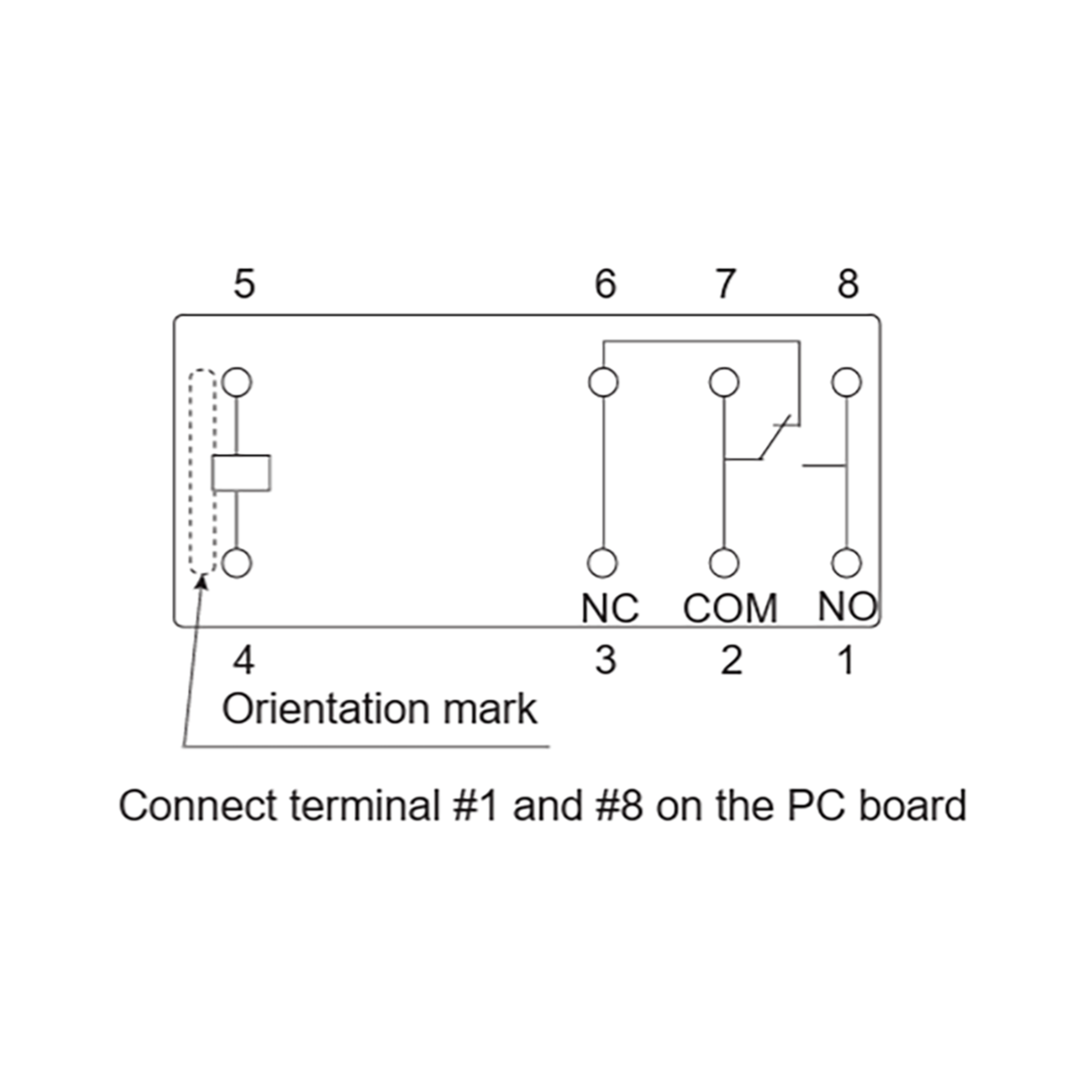
- SPDT
- Contact: Switching Current (min/typ/max)
- 16 A
- Coil: Nominal Voltage DC
- 24 V DC
- Coil resistance
- 1,440 Ohm
- Protection class RT
- RTII
- RoHS-Conform
Specifications
Close all
Other Products
All Products of the Series